



On this page
- 01Before you start
- 02What a generator set (genset) is
- 03Where it sits in the project
- 04Fuel types
- 05Configurations
- 06Power ratings: ESP, PRP, LTP, COP
- 07kW, kVA and capacity bands
- 08How to size correctly
- 09ATS, AMF and synchronisation
- 10Installation: civil, mechanical, electrical
- 11Batteries, chargers and block heaters
- 12Wet stacking (prolonged low load)
- 13Check that it works
- 14Common problems and how to fix them
- 15Applications and redundancy
- 16Frequently asked questions
- 17Talk to PSS about generators
A generator is judged twice: on commissioning day, and on the night it is actually needed. Most disappointments come from scope, not from the engine — the tank was never quoted, the ATS was assumed, or derating was ignored.
In hospitals, data centres, plants, commercial buildings and telecom sites, a utility interruption creates safety, operational and financial risk. A reliable standby solution is more than an engine and alternator: genset, ATS, starting batteries and charger, fuel storage, cooling and ventilation, exhaust, protection, earthing/bonding and remote monitoring must work as one. Undersize and large motors or load steps fail; oversize and the set may run inefficiently at light load; poor ventilation overheats; a wrong transfer arrangement leaves essential loads dark.
Before you start
- Continuous kW, PF, and the largest motor starting method.
- Rating class: ESP / PRP / LTP / COP and expected annual hours.
- Altitude, max ambient, allowed room ΔT; noise limit and canopy attenuation.
- One set or N+1 / paralleling; ATS 3- or 4-pole and neutral arrangement.
- Fuel capacity, location, bunding, refill logistics; block heater / charger requirements.
- UPS on the bus — THDi and frequency window; BMS/SCADA points and protocols.
- Commissioning: load bank, fuel quality, training; exact supply vs installation exclusions.
What a generator set (genset) is
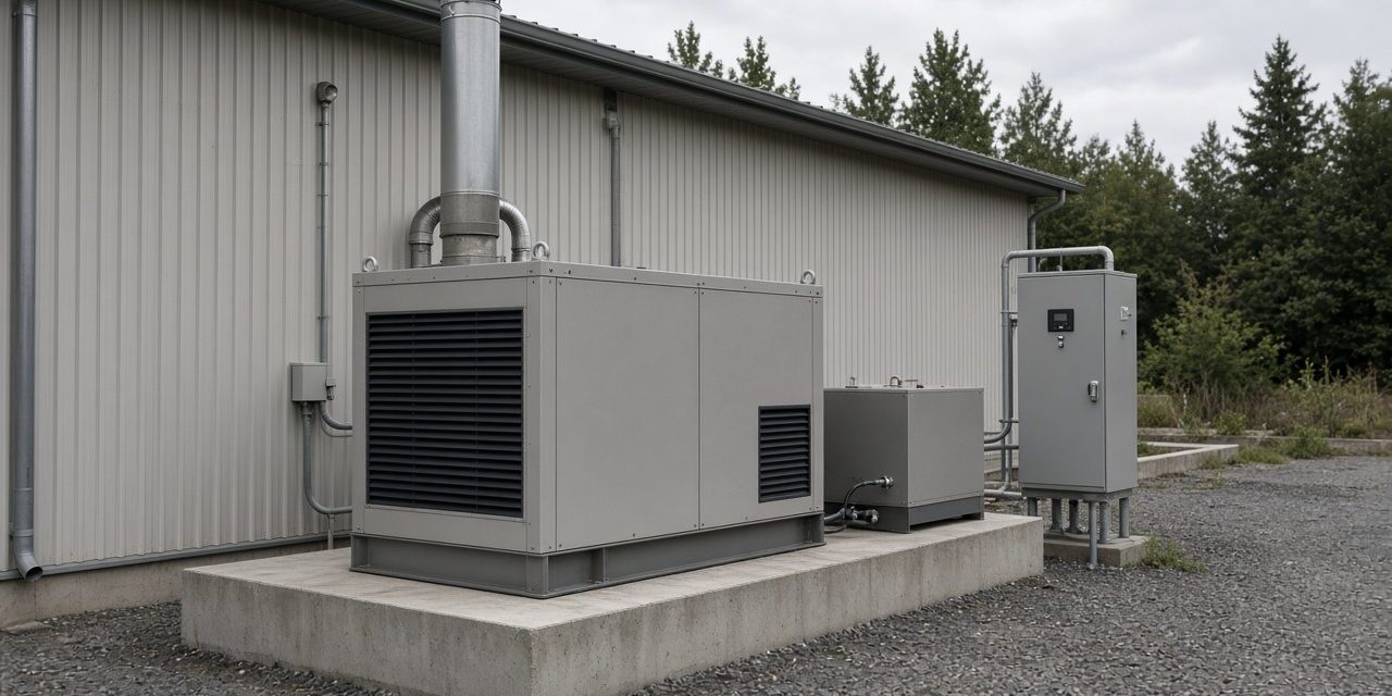
A genset converts mechanical energy into electrical energy. In a typical diesel set, an internal-combustion engine drives an alternator to produce AC. Package scope varies — some quotes cover engine, alternator, controller, radiator and base frame; others add canopy, integral tank, output breaker and charger. Compare scope, not only kVA.
Engine (prime mover)
Burns fuel to turn the alternator. Diesel is widely used for commercial/industrial standby across a broad capacity range with rapid auto-start. Check mechanical rating and speed, fuel use vs load, cooling/heat rejection, lube/coolant, starting duty, maintenance intervals, and performance at site ambient and altitude. Mechanical rating alone does not fix electrical output.
Alternator (generator end)
Converts rotation into electricity by electromagnetic induction (typically synchronous). Check voltage/frequency, kVA and rated PF, regulation and transient response, insulation/temperature rise, motor-starting and step-load capability, nonlinear/harmonic behaviour, and short-circuit characteristics for protection. Capacity is engine + alternator + controls + site conditions.
Controller
Manages start/stop, measurements, alarms and protective shutdowns. May monitor speed/hours, oil pressure, coolant temperature, battery, V/I/f/kW, availability, warnings and remote interfaces. For BMS/SCADA, confirm protocol, points and accessories — capabilities are model-specific.
Base frame, tank and canopy
Steel skid maintains alignment; sites may need isolators, flexible connections, anchors and a designed foundation. A base/integral tank is not automatically a day tank or bulk store — verify usable volume, autonomy and regulations. Outdoor packages often use weather or sound-attenuated enclosures (access, airflow, noise data at stated distance/load). Acoustic covers do not remove exhaust hazards or cooling needs.
Scope of supply
| Item | Usually in the set | Usually priced separately |
|---|---|---|
| Engine, alternator, radiator | Yes | — |
| Control panel / AMF logic | If ordered | Yes when transfer is via external ATS |
| ATS / changeover | No | Yes |
| Canopy / acoustic treatment | Optional | Yes for open sets |
| Fuel tank and piping | Small daily / base tank only | Bulk tank and transfer system |
| Batteries, charger, block heater | Often included or optional | Confirm cables, capacity, alarms |
| Civil base, exhaust run, cabling, load test | Silencer often only | Yes — foundation, full exhaust, power/control cables, commissioning |
Procurement rule: separate OEM standard package, options, and contractor installation scope. Most tender gaps are forgotten accessories, not the engine.
Where it sits in the project
Downstream of the utility, upstream of critical loads, through an ATS or AMF panel. In life-safety installations the chain may follow NFPA 110: a Type 10 system must present power at the transfer-switch terminals within 10 seconds of normal-supply failure — most of that budget is engine start and voltage build-up; transfer itself is often 0–1 s. Fuel, room, exhaust and ventilation make those 10 seconds repeatable in summer heat.
Fuel types
| Fuel | Typical use | Main considerations |
|---|---|---|
| Diesel | Commercial / industrial standby | On-site storage, fuel quality/age, emissions, noise, heat |
| Natural gas | Sites with gas infrastructure | Pressure/flow, network continuity, transient performance |
| Gasoline / LPG | Portable, residential, remote | Runtime, storage, duty approval for permanent emergency use |
| Bi-fuel | Selected industrial standby | Substitution ratio is model/load-specific — not a universal 70% |
Natural gas is not automatically more reliable than diesel in every emergency — if the same incident can cut the gas network, plan for that risk.
Configurations
Open sets — often in dedicated rooms; need weather protection, noise control, airflow, exhaust and safe access. Weather / sound-attenuated — outdoor commercial packages; enclosure must not choke cooling. Portable / trailer — temporary sites; still need safe connections, earthing, fuel handling and access control. Single vs multi-set — paralleling needs sync controls, switchgear, coordinated protection and load sharing; matching V and f alone is not enough.
Power ratings: ESP, PRP, LTP, COP
ISO 8528 defines rating classes. Exact hour limits and overload rules come from the applicable edition and the manufacturer’s rating sheet — do not treat every brochure claim as universal.
| Rating | Intended duty | Typical notes |
|---|---|---|
| ESP — Emergency Standby | Variable load during utility outage | Limited annual hours (often quoted ≤200 — verify model); not unrestricted continuous duty |
| PRP — Prime | Variable load, extended / unlimited hours | Remote sites, primary generation; average load / overload per datasheet (do not assume universal 70% / 10%) |
| LTP — Limited-Time Prime | Variable, peaking | Time-limited (often ≤500 h/yr — verify) |
| COP — Continuous | Defined constant load, unlimited hours | No overload unless OEM states otherwise |
The same machine may show e.g. 1,000 kVA ESP and 900 kVA PRP — illustrative only, not a conversion formula. Never compare one supplier’s standby rating with another’s prime as if equal. State the required class in the RFQ.
An ESP set used as the site’s only year-round power source is outside its rating from day one.
kW, kVA and capacity bands
- kW — real power. kVA — apparent power. PF — kW / kVA.
- Three-phase:
kVA = √3 × V_L × I_L / 1000;kW = kVA × PF. - Example: 1,000 kVA at PF 0.8 → 800 kW. Stay within kVA, kW, current and thermal limits. Load PF is not always 0.8.
Orientation only (not a load study): ~5–20 kVA small loads; 20–60 shops/small offices; 60–150 larger commercial; 150–350 medium buildings/workshops; 350–750 factories/pumping; 750–1,500 large facilities; above 1,500 major plants/data centres/multi-set. A small site with a large motor may need more kVA than a bigger building of resistive load.
How to size correctly
Start from a load study, not the main-breaker rating.
- Essential loads — emergency lighting/life-safety, critical IT/telecom, security, selected pumps/ventilation, fire pumps where required, selected lifts per project/code.
- Load schedule — kW/kVA, V/phase/f, FLA, PF, starting method and inrush, duty, simultaneous operation; include UPS, VFDs, rectifiers.
- Running demand — simultaneous scenarios; no blind nameplate sums, no undefended diversity.
- Motor starting / load steps — DOL often ~5–7× FLA; soft starters/VFDs change the picture; get OEM transient voltage/frequency data for large motors.
- Environment — ambient, altitude, airflow, fuel, PF, harmonics. In hot climates verify output and cooling at design temperature/altitude. Typical planning derates (confirm OEM table): ~1% per 100 m above ~1,000 m; ~1–2% per 10 °C above ~40 °C — engine and alternator may differ.
- Rating + margin — ESP/PRP/LTP/COP; allow growth when justified — there is no universal “always +20–30%” rule.
- Whole system — genset, ATS/switchgear, cables/protection, fuel, cooling/exhaust, batteries/charger, earthing/neutral switching, monitoring.
UPS on the same bus: thyristor rectifiers are distorted, low-PF loads; the 1.5–3× rule of thumb is wide — get the UPS vendor’s written figure. Set the UPS frequency window to accept generator drift or it may go to battery with a healthy set running.
Fuel autonomy:
Runtime (h) ≈ usable litres ÷ L/h at the relevant load
. Example: 400 L usable ÷ 40 L/h = 10 h. Diesel often ~0.20–0.30 L/kWh at full load (~210–250 g/kWh). A 200 kVA set at 0.8 PF → 160 kW → ~40 L/h → ~320 L for 8 h plus ullage (~×1.1). Nominal tank ≠ usable volume. Plan filtration and fuel turnover — diesel ages.
ATS, AMF and synchronisation
ATS transfers designated load between utility and generator: detect source failure → start genset → stabilise → transfer to emergency → after utility OK for the hold time, retransfer → cooldown/stop. Select for V, I, poles, short-circuit/withstand, switching arrangement; do not assume protection is “included”.
AMF is the logic that detects mains failure and coordinates start/transfer — in the genset controller, ATS controller, or both. Specify who monitors mains, who starts, who transfers, who returns.
Paralleling: e.g. a ~4 MW need might evaluate four ~1 MW sets (illustrative). Sync voltage, frequency, phase sequence and angle; then share load. Multi-set ≠ automatic N+1 — remaining capacity after a defined failure must still carry the required load. Switchgear, fuel, cooling and controls must support the availability target.
| Feature | ATS | Synchronisation / paralleling |
|---|---|---|
| Purpose | Transfer between sources | Operate compatible sources together |
| Typical | Utility + one genset | Multiple sets / coordinated sources |
| Control | Source monitor + transfer logic | Sync, load share, coordinated protection |
ATS commonly follows IEC 60947-6-1 practice; confirm poles (3 vs 4) and neutral switching with the earthing design.
Installation: civil, mechanical, electrical
Foundation — support static weight, dynamic forces, anchors; design from structure and OEM data — not a universal “pad = 1.5× genset weight” rule. Provide isolators, access, drainage, delivery path; rooftops need structural review.
Clearances — filters, batteries, radiator, panels; keep exhaust out of air intakes; allow fuel and emergency access.
Ventilation — combustion air + radiator heat rejection. Check louvre losses, attenuators, recirculation, room ΔT (OEM limit often ~8–10 °C). Open sets ~95–105 dB(A) at 1 m; canopies often cut ~20–30 dB(A) — use declared data.
Exhaust — pipe, flex, supports, silencer, insulation; stay within OEM backpressure; discharge safely away from intakes.
Fuel — base / bulk / day tank, transfer pumps, valves, level, containment/fire provisions per regulation. Usable volume and max demand matter.
Earthing / bonding / neutral — depend on winding configuration, facility earthing, whether ATS switches neutral, and code. Wrong N–E bonding creates parallel paths or confuses protection — design, do not copy.
Cables and protection — size for current, drop, method, ambient, grouping, short-circuit; generator fault current differs from utility. Review output breaker, ATS ratings, selectivity, isolation. Route control away from noisy power where needed.
Batteries, chargers and block heaters
Standby sets may sit idle for months — starting reliability is critical. Size batteries and charger for cranking duty, ambient and OEM rules; check terminals, charging voltage, alarms and crank tests. Weak batteries are a common start failure — diagnose, do not assume a universal failure rate.
A block / jacket-water heater warms coolant while stopped — better cold starts and faster load acceptance. Maintain the OEM/thermostat temperature — do not assume every site must hold exactly 40 °C. A heater does not guarantee a stated start time; the whole start/transfer chain must be designed and tested.
Wet stacking (prolonged low load)
Wet stacking is associated with some diesel operating patterns: unburned fuel/carbon/oily residue in the exhaust, often after long light-load running when the engine never reaches intended combustion conditions. Symptoms (dark/oily residue, smoke, deposits) can have other causes — follow OEM diagnosis.
There is no universal low-load threshold for every engine. Prevent by correct sizing, avoiding prolonged operation below OEM recommendations, reviewing duty cycle, and using an approved load bank when the maintenance/commissioning plan requires it. “Run at 80% for a few hours” is not a universal cure — load, duration and action depend on the engine and OEM instructions.
Check that it works
- Fluids, batteries/charger, connections/earthing, exhaust supports, airflow and breaker/controller settings verified before first start.
- No-load: start behaviour, V/f, alarms, vibration, leaks, noise.
- Load: stepped load (load bank if site load is insufficient) with defined steps, duration and V/f limits.
- ATS: simulate approved mains failure — detect → start → stabilise → transfer → retransfer → cooldown; protect critical loads during tests.
- Datasheets, drawings, settings, test reports, O&M, warranty, PM schedule, training and emergency procedures handed over.
Common problems and how to fix them
Does not start / slow crank
Alarms, battery/charger, E-stop, fuel, start permissives.
Runs but no output / ATS no transfer
Breaker, excitation, ATS mode/interlocks, source acceptance.
Stops under load / overheats
Overload, oil/coolant, fuel restriction, airflow recirculation.
V/f unstable or hunting
Governor/fuel air, load steps, excitation; speed ↔ frequency.
Smoke / residue / won’t start large motors
Engine diagnostics, wet-stack risk, transient/starting study.
Classic site mistakes
ESP set run as sole power for thousands of hours; ATS missing from the quote; undersized ventilation; ignored exhaust backpressure; fuel left a year without filtration; no load-bank test so faults above 50% stay hidden. Never bypass protective shutdowns.
Applications and redundancy
Commercial high-rise — selected emergency lighting, lifts, security, IT, life-safety, essential HVAC. Hospitals — strict transfer/testing/redundancy per healthcare rules. Data centres — often multi-set, UPS coordination, sync panels, remote monitoring. Industry — motors, restart sequences, harmonics. Water/wastewater — pump starting sequences and remote alarms. Residential/small commercial — often essential circuits only.
N = capacity for the defined load. N+1 = one spare unit so a defined single failure still leaves enough capacity — only if remaining sets, ATS, fuel and distribution actually support that scenario.
Frequently asked questions
Generator vs genset?
“Generator” may mean the alternator alone; a genset includes the prime mover and package — define scope in the contract.
Does 500 kVA standby equal 500 kVA prime?
Not necessarily — compare rating class and OEM output.
Is 100 kVA enough for 100 kW?
Not at PF 0.8 (→ 80 kW) without further starting/derating checks.
Size to 100% of the main breaker?
Not automatically — use a load study; many projects feed a dedicated emergency distribution.
Why avoid oversizing diesel?
Prolonged low load risks inefficiency and wet stacking where OEM limits are breached.
Is a block heater always required?
Depends on climate, engine, spec and OEM — improves cold start/load acceptance when needed.
Does every standby set need an ATS?
No — some use manual transfer; permanent auto-standby usually does.
Runtime on one tank?
Usable volume ÷ L/h at actual load, with reserve.
Can sets run in parallel?
Yes with designed sync, protection and load share.
How often to test?
OEM schedule + applicable standards + facility plan — include start, transfer and load capability as required.
Talk to PSS about generators
PSS designs, installs, and maintains standby generator systems, from load studies and ATS selection through commissioning and load-bank testing. Contact the PSS team to book a first site survey.
