



On this page
- 01Before you start
- 02Where cabling sits in the project
- 03Main components
- 04Copper categories: Cat5e, Cat6, Cat6A, Cat8
- 05Shielding: U/UTP, F/UTP, S/FTP
- 06Solid-core, stranded and conductor material
- 07Ethernet data rate vs cable frequency
- 08PoE and copper selection
- 09Fiber backbone
- 10Recommended copper by application
- 11Sizing rules on site
- 12Installation, testing and certification
- 13Check that it works
- 14Common problems and how to fix them
- 15Frequently asked questions
- 16Talk to PSS about networks
Every system in a building — cameras, doors, intercom, PA, fire alarm, BMS, parking — either speaks over copper or fiber, or it does not speak at all. The network is not “the IT part”; it is the physical layer that carries every other system’s data and, with PoE, most of their power. Structured cabling is the passive plant: cable, outlets, patch panels, backbone links, containment, racks and earthing. Once closed behind finishes, it serves 15–25 years. A category chosen in one week becomes a constraint for the next two decades.
Before you start
- Maximum run length per device, and where the telecom rooms sit.
- Whether anyone requires 10G readiness over a full 100 m channel.
- Solid bare copper confirmed — not copper-clad aluminium (CCA).
- Shielded or unshielded, and who owns bonding and earthing.
- Devices per switch, and total PoE draw versus the switch’s total budget.
- Existing containment, and who owns it.
- Lifts, VFDs, generators or power risers along the route.
- VLANs and subnets IT will allocate, and who configures the switches.
- Who certifies the cabling and issues permanent-link test reports.
- Fiber between buildings or floors — OM3, OM4 or OS2.
- Fire performance for escape routes (LSZH, circuit integrity).
Where cabling sits in the project
Cabling is the first work on site and the last thing anyone can fix cheaply. Design it before ceilings close, before finishes, and before systems are ordered — cable category dictates switch port speeds, PoE capability and even rack depth. Sequence: containment and pathways → copper and fiber pulling → termination and labelling → certification → system commissioning. If cabling design follows the camera schedule, you will pull cable through a finished corridor.
Main components
- Horizontal copper — from the telecom-room patch panel to the outlet or device, as a permanent link.
- Backbone — fiber between buildings, floors and main telecom rooms.
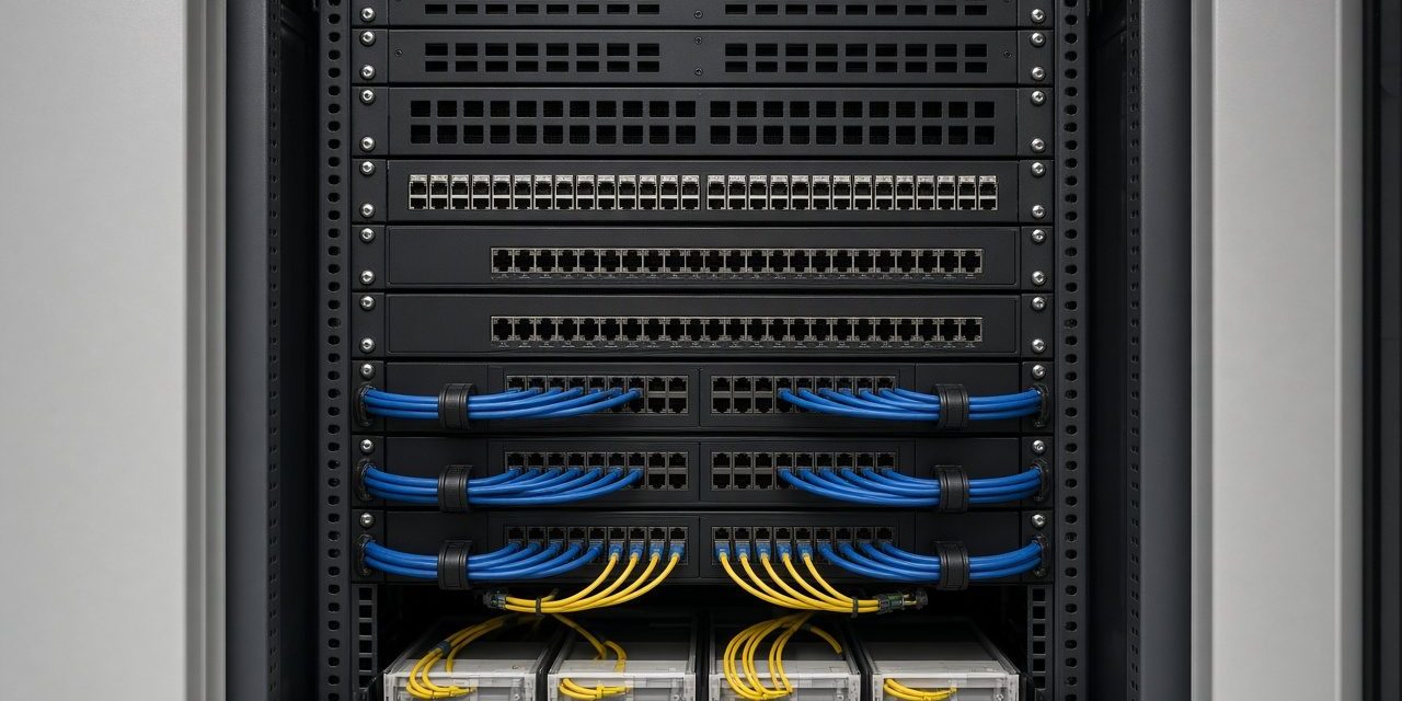
- Patch panels and racks — 19-inch, 42U, with vertical and horizontal cable management.
- Containment — trays, trunking, conduit, risers, floor boxes.
- The active layer — PoE switches, aggregation switches, routers, firewalls: bought by IT or by the security integrator, governed by the same cable plant.
- Earthing and bonding — often forgotten, always required for shielded cable and racks.
Copper categories: Cat5e, Cat6, Cat6A, Cat8
Unshielded twisted pair (UTP) connects workstations, IP phones, printers, wireless access points, cameras, access-control devices and switches. Four twisted pairs reduce interference and crosstalk. Categories differ in specified frequency bandwidth, supported Ethernet applications and long-term fit. The most common enterprise choices are Cat5e, Cat6 and Cat6A. Cat8 is for short, high-speed data-centre links.
| Feature | Cat5e | Cat6 | Cat6A | Cat8 |
|---|---|---|---|---|
| Specified bandwidth | 100 MHz | 250 MHz | 500 MHz | 2,000 MHz |
| Common Ethernet application | 1GBASE-T | 1GBASE-T; higher speeds where supported | 10GBASE-T | 25GBASE-T / 40GBASE-T |
| Typical maximum channel length | 100 m | 100 m for 1 GbE; 10 GbE typically 37–55 m | 100 m for 10 GbE | 30 m for supported 25/40 GbE |
| 1 Gigabit Ethernet | Up to 100 m | Up to 100 m | Up to 100 m | Supported |
| 2.5GBASE-T / 5GBASE-T | May be supported over qualified cabling | May be supported over qualified cabling | Up to 100 m under applicable specs | Supported within applicable limits |
| 10GBASE-T | Not a standard design choice | Limited distance; subject to qualification | Up to 100 m | Supported within specified channel limits |
| Typical deployment | Existing networks; basic connectivity | Offices; general enterprise access | New enterprise cabling; PoE-heavy sites | Short high-speed data-centre links |
| Future capacity | Basic Gigabit | Moderate upgrade potential | Strong choice for 10 Gigabit access | Specialized short-distance high speed |
Distances refer to compliant channels. Actual performance depends on the standard, installation quality and environment.
The 100 m channel rule. ANSI/TIA-568 defines a 100 m channel: up to 90 m of permanent link plus 10 m of patch cords at both ends. That is the length at which the standards guarantee the application.
- Cat5e — Gigabit over 100 m; still common in existing offices. For new long-life installs, weigh Cat5e against higher categories and the cost of later replacement.
- Cat6 — more bandwidth than Cat5e; Gigabit over 100 m; 10GBASE-T often up to about 55 m. Use Cat6A when 10G must be guaranteed over 100 m.
- Cat6A — 10GBASE-T over a full 100 m channel; stronger alien-crosstalk performance; larger cables that need more conduit and bend-radius planning.
- Cat8 — 25G/40G over up to 30 m in data centres. Not the default for general building horizontal cabling.
Shielding: U/UTP, F/UTP, S/FTP
Category and shielding are separate. A cable may be Cat6 U/UTP, Cat6A F/UTP or Cat6A S/FTP. Informal “STP” labels are often inconsistent.
| Cable construction | Shielding arrangement | Main consideration | Typical application |
|---|---|---|---|
| U/UTP | No overall shield; pairs unshielded | Simple install; relies on design and separation from interference | Offices and general commercial networks |
| F/UTP | Overall foil; pairs unshielded | Overall shield when correctly installed and bonded | Environments needing extra interference control |
| S/FTP | Overall braid plus foil around each pair | Strong shielding; extra install and bonding work | Industrial, high-density and demanding sites |
A shielded cable with a floating screen is an antenna. Near VFDs, lifts and power risers, a correctly bonded shielded system earns its cost.
Solid-core, stranded and conductor material
Solid-core — one solid copper wire per conductor; for permanent horizontal links. Lower attenuation; not for frequent movement.
Stranded — multiple strands; for patch cords. More flexible; patch length counts in the channel. Using patch cords as permanent links is a common site mistake.
Conductor material:
- Solid bare copper — standards-compliant structured cabling.
- Copper-clad aluminium (CCA) — higher resistance; not equivalent under PoE. Do not choose cables only by the printed Cat5e/Cat6/Cat6A label.
Ethernet data rate vs cable frequency
Ethernet data rate is the link speed (1 Gbps, 10 Gbps). Cable frequency bandwidth (MHz) is the frequency range over which the cabling meets transmission requirements. Cat6A at 500 MHz supporting 10GBASE-T does not mean the cable runs at 500 Mbps or 500 Gbps.
PoE and copper selection
Power over Ethernet feeds cameras, access points, VoIP phones and supported access-control devices on the same pair as data.
| PoE type | Standard | Max power at PSE | Typical power at PD | Pairs | Typical context |
|---|---|---|---|---|---|
| Type 1 | IEEE 802.3af | 15.4 W | 12.95 W | 2 | Basic PoE devices |
| Type 2 | IEEE 802.3at (PoE+) | 30 W | 25.5 W | 2 | Higher-power APs and cameras |
| Type 3 | IEEE 802.3bt | 60 W | 51 W | 4 | Higher-power network devices |
| Type 4 | IEEE 802.3bt | 90 W | 71.3 W | 4 | High-power APs and supported equipment |
PSE is the switch; power at the PD is lower because of cable loss. Category alone does not set PoE capacity — resistance, gauge, bundling, temperature and switch budget matter. Cat6A is often practical for new, dense PoE installs.
Fiber backbone
OM3 multimode carries 10GBASE-SR to about 300 m; OM4 to about 400–550 m; OS2 single-mode carries 10GBASE-LR to 10 km. Multimode for the building backbone; single-mode for campus and between buildings.
| Medium | Wavelength / frequency | 1G / 2.5G | 10G |
|---|---|---|---|
| Cat5e U/UTP | 100 MHz | 100 m | Not a design choice |
| Cat6 U/UTP | 250 MHz | 100 m | ~37–55 m |
| Cat6A F/UTP or S/FTP | 500 MHz | 100 m | 100 m |
| OM3 / OM4 fiber | 850 nm | 550 m | 300 m / ~400–550 m |
| OS2 single-mode | 1310 nm | 10 km+ | 10 km (LR) |
Recommended copper by application
| Application | Typical recommendation | Reason |
|---|---|---|
| Existing 1 Gbps office network | Cat5e or Cat6, subject to testing | Suitable for compliant Gigabit Ethernet |
| New commercial office installation | Cat6 or Cat6A | Depends on lifecycle, capacity and specification |
| 10 Gbps Ethernet over 100 metres | Cat6A | Designed for full-distance 10GBASE-T |
| IP CCTV with PoE | Cat6 common; Cat6A for higher capacity / future-ready | Supports data and power on the same channel |
| High-performance wireless access points | Cat6A where required by the AP uplink | Greater capacity for demanding deployments |
| Short high-speed data-centre copper | Cat8 or compatible DAC, depending on equipment | Specialized short-reach high-speed links |
| High-power PoE installations | Properly specified Cat6 or Cat6A with verified power and thermal design | Manages electrical and thermal constraints |
These are starting points, not substitutes for the project specification.
Sizing rules on site
PoE budget. Sum the actual draw of every device, add 25–30% headroom, and compare against the switch’s total PoE budget — not ports × per-port limit. Twenty-four cameras at 12 W draw 288 W: a 24-port switch with a 370 W budget is adequate; one with 190 W is not, even if every port is labelled “PoE+”.
Uplink. A 24-port switch fully loaded with 4 MP cameras at 4 Mbps pushes close to 1 Gbps of steady traffic. Beyond roughly 16 camera ports on one switch, specify a 10G uplink.
Cable heating. Bundled PoE cables warm up. Do not strap 40 PoE cables into one tight bundle in a hot riser without checking ampacity and LP rating where required.
Separation from power. Keep at least 300 mm from power cables, cross at 90°, and use shielded cable or metal conduit where distance cannot be held — never share a conduit with a 220 V circuit.
VLANs. Cameras, recorder, management and office/guest each get their own VLAN and subnet. A VLAN without inter-VLAN rules is only a label.
Labelling. Every link gets a unique ID at both ends matching the drawing and the certification report (TIA-606 style).
Installation, testing and certification
- Maintain the manufacturer’s minimum bend radius.
- Avoid excessive pulling tension and cable crushing.
- Preserve pair twists close to termination.
- Maintain separation from power cables.
- Use compatible jacks, patch panels and patch cords.
- Bond and earth shielded systems correctly.
- Label both ends of each permanent link.
- Test with suitable field-test equipment.
A wire-map proves wiring errors; it does not prove category performance. For certified projects, test each permanent link or channel to the specified standard, fix failures before handover, and test PoE on the actual device. Cat6A also needs alien-crosstalk consideration.
Check that it works
- Permanent-link or channel reports pass for the specified category.
- No run exceeds the 100 m channel without a designed fiber or media-conversion step.
- Total PoE draw sits under the switch budget with headroom.
- Uplinks match camera load; VLANs separate cameras from office traffic.
- Both ends of every link are labelled and match the as-built.
Common problems and how to fix them
Runs beyond 100 m “because it works”
It works until acceptance testing. Redesign with a telecom room closer, fiber backbone, or a shorter permanent link.
CCA sold as Cat6
High resistance; fails under PoE. Specify solid bare copper and reject CCA on delivery.
Patch cords used as permanent links
Replace with solid-core horizontal cable and keep stranded cords for patches only. Leave a service loop at the outlet.
Data strapped to power for 30 m
Separate trays or 300 mm clearance; cross at 90°. Shield or metal conduit where clearance fails.
No spare capacity in the riser
Plan spare conduits and tray fill for the next system before finishes close.
Floating shield or unearthing rack
Bond screens and rack correctly at both ends. A floating shield becomes an antenna.
PoE budget checked per port only
Cameras reboot when heaters cut in. Size against total switch watts, not the sticker on each port.
Cat8 specified for general horizontal cabling
Use Cat6A for 10G over 100 m in buildings; reserve Cat8 for short data-centre links.
Frequently asked questions
Is Cat6 enough for new camera runs?
Often yes for Gigabit PoE cameras. Choose Cat6A when you need 10G over 100 m, dense high-power PoE, or a longer service life without re-pulling.
Does shielding always beat U/UTP?
No. Shielding helps only when connectors, panels and bonding are correct. In quiet offices, well-designed U/UTP is usually enough.
Is 500 MHz the same as 500 Mbps?
No. Megahertz is the cable’s specified frequency range; gigabits are the Ethernet application. Do not mix them in the specification.
Who should certify the cabling?
A tester with suitable field equipment, issuing permanent-link or channel reports to the project standard before system commissioning.
Multimode or single-mode between buildings?
OM3/OM4 multimode for shorter building backbones; OS2 single-mode for campus and longer building-to-building links.
Talk to PSS about networks
PSS designs, installs and certifies networks and infrastructure under cameras, access control and the rest of the site. Contact the PSS team to book a first site survey.